


In 2014, the Iowa Department of Transportation (DOT) began formally documenting early-age bridge deck cracking and its negative influence on service life. Many best practices were implemented in an effort to prevent this phenomenon, but given the complexity and volume of project characteristics that influence early-age cracking, instances still occurred at a frequency higher than desired, leading the Iowa DOT to explore mitigation solutions in addition to prevention.
Because early-age cracking is challenging to prevent, Iowa DOT commissioned WJE to investigate how the bridge industry addresses early-age cracking, identify appropriate bridge deck preservation treatments that mitigate the impacts of early-age cracks, conduct life-cycle cost evaluation of the various treatment options, and propose a data-driven matrix of treatment options to minimize bridge life-cycle costs for cracked bridge decks.
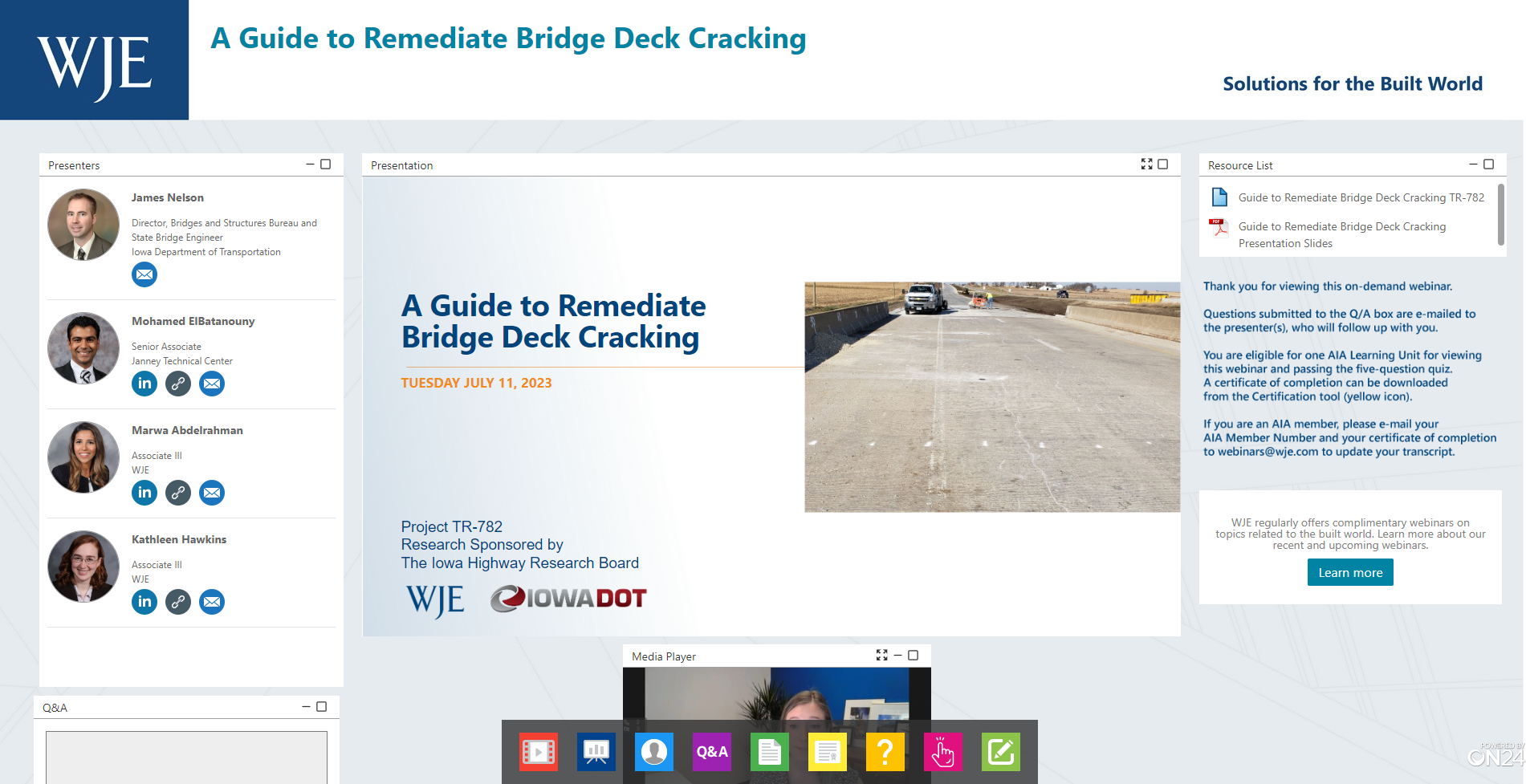
In this webinar, Director of Iowa DOT Bridges and Structures Bureau James Nelson, WJE structural engineer Mohamed ElBatanouny, and WJE materials engineers Marwa Abdelrahman and Kate Hawkins present the findings and conclusions from this study.
By the end of the webinar, you will be able to:
- Identify characteristics that can contribute to the initiation of early-age bridge deck cracking
- Explain the effects of early-age cracking on bridge deck durability and service life
- Compare various bridge preservation treatments to address bridge deck cracking
- Describe the life-cycle cost analysis process used to create data-driven decision matrices
more to learn
View this webinar in our interactive audience console to earn 1 AIA HSW learning unit, access related resources, submit questions to the presenters, and download a certificate of completion.
Mohamed ElBatanouny, Associate Principal and Unit Manager
Kathleen A. Hawkins, Associate III
LIZ PIMPER
Hello everyone and welcome to today's WJE Webinar, A Guide to Remediate Bridge Deck Cracking. My name is Liz Pimper and I'll be your moderator. During the next hour, director of Iowa DOT Bridges and Structures Bureau, Jim Nelson, WJE structural engineer, Mohamed ElBatanouny, and WJE materials engineers, Marwa Abdelrahman and Kate Hawkins will present the findings and conclusions from a study of appropriate bridge deck preservation treatments to mitigate the impacts of early age cracks. This presentation is copyrighted by Wiss, Janney, Elstner Associates. Now I will turn it over to Jim to get us started. Jim?
JIM NELSON
Thank you. Good day everyone. Welcome to the webinar on the Guide to Remediate Bridge Deck Cracking. As Liz said, my name is Jim Nelson. I serve as director of the Bridges and Structures Bureau at Iowa DOT. I also chair the AASHTO Committee on Bridges and Structures Bridge Preservation Technical Committee. Extending bridge service life through preservation has become a key interest of mine to counteract the demands of our aging bridge inventory. The work done in this project has a good potential for helping preserve our bridges and keep the bridge network in Iowa in a state of good repair. This project was funded by Iowa Highway Research Board and the Highway Research Board assigned this as project number TR-782. So you may hear us referring to the work as project TR-782 for shorthand. In order to satisfy learning requirements for AIA for continuing education, we need to present our learning objectives.
Those are given on this slide that you can read. As Liz mentioned, the PDF of the presentation will be made available after this webinar and so you can review these learning objectives in more depth or review the content of the presentation. What is the problem that we're trying to deal with here? I think this photo in this slide illustrates the issue that we're facing and what this is is the underside of the eastbound Iowa tube over the Missouri River overflow bridge deck in one span. The red arrow points to a location of efflorescence. That efflorescence is indicative of moisture leaking through a full depth transverse crack in the bridge deck and leaving soluble minerals on the surface on the underside of the bridge deck. To the right of the photo, you'll notice the bridge inspector's sketch who's documented all the full-depth transverse cracking in that bridge deck in that single span, a pretty significant amount of cracking.
Using engineering judgment, we are planning a thin polymer overlay to mitigate this bridge deck cracking on this bridge deck, but it's a topic that we've needed to study and work to improve. In 2014 we really started a formal process of investigation through an Iowa State University and Intrans study on the causes of bridge deck cracking. The one thing that's been impressed upon me by that study is that early-age bridge deck cracking is a multidisciplinary problem and it's influenced by the structure design details. It's influenced by the materials used, it's influenced by the construction means and methods, and it can even be influenced by the weather just on the day that the bridge decks is being cast. The problem requires a multidisciplinary approach to finding a solution, but even with a sound multidisciplinary approach to prevent early-age bridge deck cracking, I don't think that we are likely to be a hundred percent successful in preventing the cracking because of the large number of factors contributing to the problem. Because of that, we need policy on when and how to remediate early-age bridge deck cracking. The TR-782 project conducted by WJE provides a scientific data-driven and lifecycle cost analysis justified response on what to do about early age bridge deck cracking.
For the presentation outline today, I'm going to give you the project introduction. After that, I'm going to turn it over to Kate Hawkins who's going to talk about the project TR-782 objectives following Kate, we'll hear about service life modeling from Dr. Marwa Abdelrahman and then finishing up, we'll hear from Dr. Mohamed ElBatanouny on data-driven decision trees and summary and recommendations.
Continuing on with the introduction, the types of concrete cracking at an early age are numerous and there's various causes. Plastic shrinkage cracks often occur near the surface of flush replace when the moisture evaporates from the surface. We mitigate that with good curing practices and we've done a little bit of change in our curing practices recently to hopefully improve the results we get. Plastic settlement cracks can occur when concrete continues to consolidate under its own weight after initial placement. Plastic settlement cracks are not often seen in bridge decks and may be more prevalent in larger masses of concrete placement. Autogenous shrinkage cracks are due to reduction in volume caused by a chemical process of hydration of cement. This is probably one of the contributing factors to some of the early-age cracking that we are seeing. Drying shrinkage cracks are caused by the loss of moisture from the cement paste once the deck is exposed to the environment.
This is likely also another contributing factor for us. These two shrinkage crack mechanisms would probably not exist if the concrete wasn't restrained. What I'm saying by that is that if the deck was just a volume of concrete free in space to expand and contract on its own, the shrinkage cracks would not develop. There's another factor and that is the restraint. What we're talking about in this presentation are bridge decks cast on beam bridges, either pretension, prestress, concrete beams or steel beams, typically continuous welded girders. There's mechanisms of restraint because we're wanting to create composite sections with those systems. For example, on the top of our pretension pre-stressed concrete beams, we have a roughened surface and we have shear strips that are providing restraint. On the steel beams, we have generally shear studs that are providing restraint and maybe a little bit of friction between the deck and the top of the flange. I think because of the different restraint conditions, we do see some differences in the amount of early age bridge deck cracking on different beam types. Finally, there's thermal cracks caused by different heats of hydration, different curling rates, and ambient temperature changes
Later age cracking is also an issue and you're probably familiar with steel corrosion causing cracking. There's also freeze saw distress which we mitigate through proper air entrainment of our concrete. Then Alkali-Silica reaction, ASR conventionally heard, where we mitigate that through our aggregate specifications so those are not big issues in Iowa. Then finally, structural loading cracking, which often manifests itself in the cracking over the piers in the negative moment regions. These types of cracking are not a focus of this research. Really the research is focused on that early age cracking that we initially get.
How big of a problem is this? Iowa DOTs, Ahmad Yusef and Mike Knapp and the Bridges and Structures Bureau conducted the desktop study to investigate this problem. They focused on bridges constructed from 2015 to 2019 and the reason... They did this work in 2021 and the reason they focused on that time period of bridge decks is that there were new bridge decks that had inspection records. Of the bridges that they looked at, which totaled 136, about a quarter of them were steel beam bridges, which is represented by the blue pie in the graph up there. About three-quarters of them are pretension pre-stressed concrete beams. The results of their investigation are shown in these two graphs with the top graph being steel beam bridges. The blue bar is designating the number of bridges constructed in each year shown, and then the red bar is the number of those bridges in that group that had cracking. You can see the number we have for steel beam bridges and then on the lower graph is the pretension pre-stressed concrete beam bridges with the same data with blue bar showing bridge decks constructed in the red bar bridge decks with cracks.
To sum up that data, we had 105 pretension pre-stressed concrete beam bridges constructed from 2015 to '19 and roughly about half of them had cracked decks. In the steel beam category, we had a smaller sample of 31 steel beam bridges constructed, and there we had about one-fifth of the bridge's exhibit cracks. The cracking in the decks varied in terms of severity and so we've also classified severity as either no cracking, mild cracking, moderate cracking, or severe cracking. This graph on this page is showing all bridges constructed both pretension, pre-stressed concrete beam, and steel bridges. In their investigation looking at the inspection records, they classified each of the different levels of cracking. I'm giving examples here. The first sketch on the left is level zero because there is no cracking, so that would be none. The sketch on the right exhibits just a mild level of cracking and so there are very few cracks on the underside of that bridge deck, but there are some. Examples of moderate-level cracking are shown on the slide, on the sketch on the left, and then severe cases shown on the sketch on the right.
Looking at that data, again, overall we had about 41% cracked decks when you're looking at both bridge types. About 8% of it was mild, 15% moderate, and 18% percent severe. We've looked into solutions and we've made some changes recently. We've been, as I said, formally studying this since 2014 and implemented a variety of things. One of the things that we recently did was update our standard specifications to specify a seven-day wet cure for concrete bridge decks that are cast using Portland cement concrete. We've also been constructing bridges with high-performance concrete since the early 2000s and that specification from the start had a seven-day wet cure, but we had a legacy specification for our conventional concrete bridge decks that only had a three-day wet cure. We recently modified that so now that all those bridge decks are getting a seven-day wet cure, which I think to be probably at the bottom end of the range of best practices, which probably recommends a seven to 14-day wet cure.
The other thing that we've done recently is piloted the use of non-metallic, fiber-reinforced concrete in bridge decks. So far that piloting has been going well, but we're too early in the piloting to tell how the effect is on early-age cracking. But because it's been successfully implemented in our pilots and it's extremely low cost, we're actually going to continue and expand the use and then continue to monitor over time what our early age cracking situation is. One of the things that I think is promising nationally but hasn't been implemented in Iowa yet is internal curing. Unfortunately, Iowa doesn't have readily available sources for the expanded shale aggregate that folks typically use for internal curing. We would have to import it and, at this time, we don't think it's practical or cost-effective to import that type of aggregate. What we're looking into is investigating admixtures for internal curing concrete. We've got two current research projects that are looking into that topic. Even with trying to prevent early-age bridge deck cracking, we still have the problem, and we need to implement bridge preservation practices for cracked concrete decks. That's where the findings of WJEs TR-782 Guide to Remediate Bridge Deck Cracking can help us. With that, I'd like to turn it over to Kate to talk about the objectives of that project.
KATE HAWKINS
Thanks, Jim. Yeah. To reiterate, the primary objective of project TR-782 was to develop a comprehensive guide for the remediation of cracked bridge decks in Iowa. The primary deliverable of this work was a decision matrix for selecting crack repairs based on technical considerations. That would be the deck condition and age and the crack characteristics, like the width and density. Then the decision matrix was also supposed to take consideration practical considerations, like cost, the amount of service life desired, and how easily the repairs could be conducted. To further support it and make it, again, more comprehensive of a guide, we wanted to include crack inspection procedures to determine the information that would go into the decision matrix and how it's collected and then guidelines on how to execute the crack repairs.
Again, to reiterate what Jim said, we kind of categorized cracking as early age versus later age. The focus of this guide is on early age. Fixing a lot of the later age cracking, that's really caused by material degradation typically and sometimes loading. Addressing that cracking would be really a temporary fix and you would really want to address the degradation mechanism. This guide is supposed to really focus on improving the durability at an early age. It's all very well and good to talk about causes of cracking, but when you have an inspector out on the field who's trying to figure out how do I describe this cracking so that we can make a decision on it, we came up with five. There are five categories that you would want to know. The first one is the orientation of the cracks with respect to traffic.
Jim showed a very nice photo very early on, and here's another one, of transverse cracking where the cracks are transverse to the direction of traffic. There's also longitudinal cracking which is parallel to traffic, and if the cracks don't really follow any particular pattern with respect to traffic, we might call them diagonal. Crack orientation is best used for describing discrete cracks, but sometimes we'll come across pattern cracking or map cracking. Noting the pattern of the cracking is also important. We also want to know the cracks spacing, and I'll get into this more on the next slide, but it generally refers to the density of cracks within the area that's being inspected or their frequency. Crack size is important, so that would be crack width, crack depth. Then lastly, there's crack activity, and this refers to whether the crack is active or dormant and active cracks are also called working cracks.
The whole idea is that the mouth of the crack, the width that you can see, will change with time. It'll open and close sometimes due to temperature, sometimes due to traffic going over the bridge deck. These generally require specialized repairs for the repairs to be effective. Sorry there. That was not considered in the guide that was considered outside of the scope. But when you're out on the bridge deck conducting the inspection, the primary things that you can determine visually are the crack orientation, the crack pattern, the spacing, and the width. You might be able to get an idea of the crack depth if you have a probe, but generally to get an accurate depiction of crack depth, you would really need to take cores which isn't very desirable.
To get a little bit more into how we would want to describe crack density, because there's a number of different ways to do it, we followed a classification that was developed for the Montana DOT by Todd Nelson of WJE, and we have four primary categories. We have mild cracking, moderate cracking, severe cracking, and very severe cracking. On the far left of this table, it's expressed in terms of length of crack per unit area of deck, which is very easy to determine in the field. In the center of the table, there's crack affected area, and this relates a little bit more to the modeling that Marwa will discuss, but essentially we assume that the crack affects the two inches on either side of it, and so that becomes an area divided by the unit area of the deck.
The last one, the last way to express it that we have here is frequency of cracks or what's their spacing. If we assume that all of the cracks are transverse cracks, which happen very frequently, how many feet are there between each crack? That's the final way we described it here. To give some examples as to what these different density categories would look like, this is an example of mild cracking, again purely based on density. The green shaded area is the unit area that we were looking at or the inspection area, and the green lines are the cracks that were noted during the inspection. This is an example of moderate cracking and, again, this is moderate cracking within the yellow shaded area. Then this is an example of severe cracking in the pink shaded area. I don't have an example of very severe cracking that's about a crack every foot, which can happen, but it's very rare. All of these are real life examples or real world examples that have been observed in the field.
Getting into crack depth, this doesn't have an exact number, but for the purposes of this study, we consider deep cracks to be cracks that directly reach the reinforcing steel as these would permit moisture and chlorides or other aggressive ions to directly reach the steel and cause degradation. Shallow cracks, on the other hand, we classified as cracks that extend a little bit into the concrete cover, but not completely so there's still some concrete protection over the reinforcing steel. Below with regards to pattern and width, again, these aren't absolute rules, but we generally characterize deep cracks as being transverse or longitudinal, discreet cracks versus shallow cracks. We consider map cracking to typically be shallow, and then deep cracks we expected to be relatively wide compared to shallow cracks.
After getting into how do we characterize and describe cracks and what information would come in from the field, we came up with a list of crack repairs that could be done and they varied from anything as minor as putting deferring maintenance or doing nothing for now or applying a water-repellent treatment to the deck surface, which would be a penetrating sealer. Also, the way to relatively robust repairs such as placing down an overlay or even replacing the deck, but we didn't consider all of these. If we took out routing and sealing as this is actually more commonly done for active cracks and it's rarely done on bridge decks. It's really a pavement crack repair method, so it would have a relatively high initial cost and require some investment for bridged deck applications. We also took out pressure injection with epoxy. This is, again, a relatively expensive crack repair and it's very good for structural repairs.
But the whole point of this is to address early age bridge cracking for durability. It was relatively economical and the need for pressure injection would be evaluated on a case by case basis. We also removed the cementitious overlays. This isn't typically done. It's very undesirable on early age decks that have just been constructed due to their expense and they have quite a bit of traffic disruption. But we kept in the premixed polymer concrete overlay. We recognize that's also a very expensive option, but it provides a relatively impermeable layer compared to the existing concrete cover and it has much less traffic disruption than cementitious overlays. Lastly, we also took out replacing the deck. It's not never done, but it would require very special investigation and extenuating circumstances to be cost-effective, which, again, is something that should be considered on a case by case basis outside of the guide. With that, I'll turn it over to Marwa to discuss this more.
MARWA ABDELRAHMAN
Thanks Kate. To develop the decision trees, which are the main objective of this project, and to run the lifecycle cost analysis, we need first to understand what is the service life to be achieved with each of the treatment options. For that, we perform service life modeling using our in-house modeling software, WJE CASLE. We compare the different crack treatment options by looking at two threshold values. The first one is what is the time to repair? After treating the cracks, how long it takes until the bridge is due for partial depth repairs. We assume that this is when the bridge deck is showing damage over 5% its surface area. The second threshold was what is the time to replacement? We assume that this is when the bridge deck is showing damage over 20% of its surface area. We understand that these thresholds are different from one DOT to another, but we consider that 20% damage on the bridge deck weren't enough significant enough rehabilitation project that we can consider for our analysis as replacement effort.
To run the service life modeling, we conceptualize the corrosion process into two stages. The first stage is initiation time, which is the time it takes for chlorides to penetrate through the concrete cover until it reaches the depth of the enforcement and accumulated that depth to a critical concentration that we call chloride threshold. This is when the corrosion initiates. Then comes the propagation time, which is the time afterwards that the corrosion product build up on the bar service and exerts stresses on the surrounding concrete that would cause cracking and then surface damage consisting of the lamination and spalling. Our model predicts the time to damage as a submission of the initiation time and propagation time. Here with WJE CASLE, we model the initiation time and a probabilistic approach. For the propagation time, we consider it as a constant value between 10 to 15 years, considering here that we are focused on bridge decks in Iowa, which are primarily constructed with epoxy coated bars.
Since we are performing the modeling in a probabilistic approach, we consider each of the input parameter as a probability distribution. Here I'm showing the main input parameters that we have for our model. Starting with a concrete cover, we assumed an average of two and a half inches. This is consistent with typical construction of bridge decks in Iowa and we considered also the typical construction tolerances with that in defining the distribution. Then we have the diffusion coefficient and this describes the resistance of the concrete to chloride penetration and we assume the distribution for this input parameter based on the mixed designs that are typically used for the bridge decks. Also, we confirm this distribution using lab testing on concrete cores that were collected from a recently constructed bridge deck in Iowa. For the exposure conditions, we used our database of surface chloride concentration that was estimated based on numerous cores that were collected during previous investigations that WJE performed on bridge decks in Iowa. For chloride threshold, this was assumed based on the reinforcement bar type and, in this case, it's epoxy coated bars and also considering the cement content and supplements the cementitious material of typical mixes.
The output for our analysis would be that what is a percentage of damage in terms of surface area of the bridge deck with the age of the structure. If we define an end of service life criterion, in this case we defined it at 20% of damage, we can then estimate what is the service life of the bridge deck.
Here I'm going briefly over how we considered cracking in our model. For uncracked concrete, we assume the diffusion coefficient based on the typical mix design and the chloride profiles from and or diffusion testing of concrete cores. But for cracked concrete, the presence of the crack would facilitate the penetration of chlorides. We described that in our model using an elevated diffusion coefficient. In this case with the concrete mixes, as we investigated here, this value came to be two and a half times greater than that of uncracked concrete. We assume that this elevated diffusion coefficient would affect two inches on each side of the crack. This is what we called here crack affected areas. Other assumptions that we consider for our model, we considered concrete mix with no supplementary cementitious material, so no fly ash or slack. We considered epoxy coated bars and we two types of cracks, deep cracks, and that includes transfers or longitudinal cracks that reach the depths of the reinforcement, and we assume that those would have a crack width of 10 miles or wider. Also, we considered cases of shallow cracks and these we assume that those only extend to one inch within the concrete cover and have a width of five miles.
Here I'm showing the results of the baseline cases. If we consider uncracked bridge deck using the assumptions that we described earlier and we consider the end of service life criterion that we have here, we can estimate the service life of our example bridge to be 47 years. If for the shallow cracked areas, so for the areas that have shallow cracking, with a little bit higher diffusion coefficient, the service life of those crack affected areas comes down to be 25 years. For the case of deep cracks, so cracks that reaches the enforcement, the crack affected area have a service life down to 17 years. These results here highlight the effect of cracking and how it can be detrimental to the service life of the bridge deck.
We considered in our analysis different treatment options, starting from do nothing, penetrating sealers, gravity-fed polymer by crack-chasing, flood coats, hot-mix asphalt with waterproofing membrane and also polymer overlays. To consider the benefit of each of those treatments in our analysis, I grouped them here in three groups. First one is the crack treatments that provide sealing effect from chloride contaminated water and this includes sealers and waterproofing membranes. We consider that in our analysis by slowing the rate of chloride buildup, but also those sealers or membrane deteriorate over time due to wear and abrasion. We consider that in our analysis by reducing the effectiveness of those treatment options over the lifespan of the sealer, which is five years, and the lifespan of the membrane, which was assumed as 20 years in our analysis.
Second set of crack treatments here includes crack chasing and flood coats and those treatments fill the crack and restore the performance of the crack affected area to perform like uncracked concrete. For modeling, we assume that majority of those crack affected area when they are treated with those treatment options will be fully restored and will perform with a diffusion coefficient similar to uncracked concrete. Also for flood coat options, this provide also sealing effect to the deck from chloride contaminated water. We also included additional benefits similar to that for penetrating sealer when we investigated the flood code option.
The third group we have here is polymer overlay, whether we have 10 polymer overlays that are typically applied at a depth of quarter inch to three eighths of an inch over the bridge deck or premixed polymer concrete overlays. It's typically applied at deeper depth, typically at least one inch over the concrete bridge deck. Those polymer layers are relatively impermeable when compared to typical cement concrete. We modeled those or considered those in our model as discrete layer with very low diffusion coefficient. Also, we assume that those overlays lose effectiveness over time due to delamination where an abrasion and aggregate pop-out in our model. We considered lots of analysis cases of the different treatment options that I described earlier and also we investigated the timing of application of each of those treatment options. We investigated what would be the benefit if we applied them shortly after construction, so at year zero, and also two years, five, and if we waited 10 years after construction.
We looked also at what would be the effect of cracking and the effect of the different treatment options at different crack densities. We looked at the range of crack densities between zero and cracked condition up to 33% crack affected area or a cracked density of one. On the figure on the left here, I'm showing the effect of the shallow cracking in terms of the time to repair, which we defined earlier as the time where the bridge deck going to show damage over 5% over its surface area. Here with the shallow cracking we see that it has some effect on reducing the time to repair. However, it's not significant, especially at low crack tendencies, but for deep cracking, the effect of cracking is much more pronounced and much more significant, even a relatively low crack densities and crack affected area as low as two and 3%.
For the sake of time here, I'm showing the result of one example of the treatment option. Here I have the results for flood code applied at year zero. The figure on the left here, it shows the time to repair and on the right shows the time to replacement. When we apply flood coat, it increased the time until the repair would be needed or bridge deck replacement would be needed. In some cases with low crack densities, see that it even provided benefit over the untreated uncracked bridge deck case. But for cases with very severe crack densities, so crack affected area of 33%, it provided some benefit but we didn't reach the uncracked untreated condition.
Here I'm showing the results again and this time we investigated the effect of timing of the treatment application. Here were the results when we applied the treatment at year zero, but if we waited five years and applied the flood coat, the benefit that we get is less than when we applied it at year zero. If we waited even further, so if we waited 10 years, it reduces the effect or the benefit of the treatment even further, especially at higher crack densities.
We looked at the benefit of the crack treatment options at different crack densities for the different options that I described earlier. Here I'm showing just the results when the different treatments are applied at zero years. Starting with a do nothing case. As we described earlier, the time to repair is less with higher correct densities and then we're seeing similar effect with the sealer provided some benefit and extending the time till the repairs are needed. Here's the results for flood coat, hot-mix asphalt with waterproofing membrane, also for thin polymer overlay, and premixed polymer concrete overlay. All of the treatment options provided benefit over the do-nothing case and that level of benefit changed depending on what treatment options you apply and also depending on the crack density. We used all of this information to develop decision trees as Mohamed is going to describe next.
MOHAMED ELBATANOUNY
Thank you Marwa. As Marwa mentioned, we use information from the service life modeling to help us guide us in developing our decision trees. The idea here was to basically if you look at a specific bridge deck and you consider the time of treatment application, and again we consider early age, so we looked at zero, five, and 10 years. Then you look at the crack characteristics for that particular deck, which includes the cracked density and crack width, and then using the service type modeling results for the different repair options, we can get the time to repair, which is the time to get to 5% surface damage, and the time to replacement, which is the time to get to 20% surface damage. If we also have cost information for the different repair options, we can actually look into the initial cost on the lifecycle cost to help us choose the optimal repair option for that particular deck.
For the lifecycle cost analysis, we use the cost information that we collected primarily from Iowa DOT bid tables. For some of the techniques, the repair techniques that are not used in Iowa regularly, we actually looked at neighboring states to get this cost information, and then we considered the hundred-year analysis period to complete our lifecycle cost. Again, as Marwa mentioned, end of service life we assume that it is at about 20% damage. If you have a bridge deck with no cracks, that is about 47 years. In order to do a lifecycle cost, we start with assuming a price for the new deck and then we know that this deck will stay in service for about 47 years. Then this deck gets replaced and then it stays in service for another 47 years, it gets replaced again, and then at the end of the analysis period we can calculate as a value.
For the lifecycle cost analysis, we use the present value analysis. Basically, take all these costs and transform them to a present value and that will be the lifecycle cost. Then we use the service life modeling results to do the same analysis for all the different repair options. Here I'm just showing a summary of all the costs for the different treatment options and there's also a graph that compares these costs to the cost of replacing the bridge deck. As you can see, we considered the bare options with a wide range of costs, starting from about $9 per square yard for a penetrating sealer all the way down to $66 per square yard for a sampler overlay or $136 per square yard for a premixed polymer overlay. That ranges from about 1% to 15% of the cost of constructing the deck.
For an uncracked deck, again, we can use the service life modeling results to get the time to repair, which is about 35 years, the time to replacement, which is about 47 years, and then use that information to calculate the lifecycle. Again, we can use the information from all the different repair options to do the same analysis for all the options we considered. For a do nothing scenario, if we divide these spares of different crack densities that Kate mentioned in the beginning of the presentation, so mild cracking less than 0.1 feet or feet per square, that gives us about 34 years for time to repairs, 46 for time to replacement, and you can see we can calculate a lifecycle cost, which is a little bit more expensive than an uncracked condition. If we consider a higher cracked density, so moderate, between 0.1 and 0.22, you can see a reduction in your service life and also an increase in your lifecycle cost because you'll need to replace the deck more often.
Same thing with severe. You can see a reduction in your service life and actually a significant reduction here in the time to repair. This is about 60% of what you would get if you have an uncracked deck and then increase in the lifecycle cost. Then if you go to very severe, that's even further reduction in your service life and a bigger increase in your lifecycle cost. If we do this for the different repair options, so for example, if we consider a penetrating sealer, you can see that for each of the different crack densities, you get an increase in your service life if you compare that penetrating sealer application to do nothing. But you can see you also spend some money at the initial cost, and you can calculate the lifecycle cost, which is typically lower than the do-nothing scenario for all the cases.
If you then consider another case, maybe a penetrating sealer, that you reapply three times at four-year intervals, you can see a further increase in your service life compared to do nothing and also you can calculate the life cycle cost through this. Then we applied the same analysis to all the different repair options to be considered, so crack chasing, flood coat, hot-mix asphalt with waterproofing membrane, thin polymer overlay, and a premixed polymer overlay. In order for us to analyze this data from these tables, what we did is we break these tables into even a smaller tables as that considers the different crack densities. For example here, if we consider a severe crack density, so between 0.22 to 0.37 feet per feet square, and we look at the different remediation options in that category, we can basically do a comparison between all these different repair options to the do-nothing scenario.
In that case, if I apply a penetrating sealer, I will need to spend about $9 per square yard as cost for applying this treatment, but I will get about two years increase in my time to repairs, three years increase in my time to replacement, and my lifecycle cost will decrease by 2% compared to the do-nothing scenario. If then you apply another treatment, which is penetrating sealer with reapplication, you can see a higher initial cost but also a higher increase in your service life benefit extension and about the same lifecycle cost. If you do this with a flood coat, you get a significant increase in your service life, especially the time to repair, and also a lower lifecycle cost. Same for overlay, a little bit more expensive or actually three times more expensive than the flood coat, but it gives you a significant increase in your time to replacement and this is so far the lowest lifecycle cost.
Then if you consider a premixed polymer overlay, this is the most expensive option, initial cost, but it also gives you the most extension in terms of service life and it also comes at a lower lifecycle cost compared to do nothing. Another comparison we looked at is if we compare all these cases to a base case where you have an uncracked concrete deck and that was important for us because an uncracked deck we'll get to 5% damage, which is a number we assume to do partial depth repairs at 35 years. If you have a deck with severe cracking and you do nothing, basically you'll need to start fixing that deck after only 19 years in service, which is a significant reduction in that service life that we are trying to have through that deck. What we did is we did the same analysis for all the different options and, as you can see, there's a lot of red still with the penetrating sealer and the reapplications and when we get to a flood coat, we start seeing green again, which means that the flood coat compares well to the base case of uncracked concrete deck.
It basically gives you the same service life and then the polymer overlay options give you even better service life extensions in the base case of uncracked concrete deck. We did this for all the different categories and then we built these simplified decision trees. These are decision trees that can categorize the deck using the cracked density information from mild to very severe and then the crack width information too because some of the repair options will not work with larger crack width. For example, a penetrating sealer, we assume it doesn't work if you have a crack width more than 15 miles. Then we color coded this chart with green to indicate the most suitable option. We had an asterisk if the most suitable option is an overlay because this is a significant investment for a new bridge deck. Yellow indicates a suitable option, not the most suitable but a suitable option, and orange indicates the least suitable option.
This may be an option that gives you a lot of life, but it's also a high initial cost. Then pink indicates need for additional investigation. We created a chart for applying the treatments at time between zero and three years to a new bridge deck. You can see here all the different color codes. But basically, if you have a bridge deck with a crack width between five to 15 miles and you have a crack density that is mild, then your best option are do nothing or a penetrating seal. But if you have the same crack width and your crack density is severe, then you have to apply a flood coat, and you can basically apply the same logic to all these different categories that we have here. There is a lot of explanation in the report of how we did these color codes and I would encourage you to review it because there is also some limitations for using this chart.
For example, we say if you have greater than 40-mile cracks, investigate, or if you have very severe crack density, you need to investigate before you actually apply any of these recommendations while you have that amount of cracking. We did the same chart for applying the treatments at time of five years and then a similar chart for applying the treatments at time of 10 years. There are other considerations when you're selecting the repair option. One of them is traffic disruption. Some of the repair options can be put while in partial closures of the traffic. Some options are a little bit more involved and need some surface treatment or surface preparation. Also, the schedule, can you do this over a weekend or you want to do it only during nights, for example. Available budget, because the initial cost for these options again vary significantly.
Then local expertise was the different treatment options and also availability of material. We were fortunate to be able to do an example. We had the Grinnell I80 bridge deck while we were doing the project that had a problem with early cracking, so that bridge deck was about 150 feet long, about 60 feet wide. We basically went out there, did a crack map for the deck, and you can see it here, all the green lines are basically cracks. We also collected some photos of that bridge deck. Basically, what you see here is that this southern 10 feet of that bridge deck had a lot of cracking, early age cracking, before the bridge was actually open to traffic. If we apply the logic that we developed here and assume this is a deck area and calculate that summation of the crack length and calculate the crack density, that will give us a crack density of 0.02, which is mild.
In that case, you can either do nothing or put a penetrating seal. But if we only consider the 10 feet where you have most of the cracks, full lane lengths, and you calculate the crack density, that gives you a crack density of above 0.11, which is in the moderate category now. You can't do nothing anymore. Your best option is a flood coat or you can still put a penetrating seal. If you goes in around the pier and calculate the crack density, that comes up to about 0.2, which is, again, in the moderate category and same options. But if you go to the area where you have the most significant cracks, the heavier cracks, and you calculate the crack dynasties that gave you a crack density of 0.25. Now this is in the severe cracking range and your only option really is to apply a flood coat.
This showed us the importance of selecting appropriate area to calculate the crack density. Actually, Florida DOT specifies that when you calculate crack dynasties you need to investigate an area between 100 and 400 square feet and we found that this is a good range. It was actually one of the ranges that we used in this analysis here. We recommended to that that range be used for calculating crack densities. In summary, we evaluated the impact of deep and shallow cracks and different crack densities on the service life of Iowa Bridge decks using service life modeling, particularly WJE CASLE software. The modeling showed us that it is very important to repair the cracks because that will have a huge effect on the durability and the service life of your bridge decks. Also, the analysis did show that the timing of application is very important.
The earlier you affect these cracks, the better your service life extension would be because that timing had the significant effect on the service life extension benefits. Finally, we were able to develop data-driven decision trees that are specific to Iowa because we did use Iowa exposure conditions and Iowa materials and also Iowa design specifications in this project. But these decision trees were developed with the ideas that you can select the optimal repair options for a bridge deck cracking problem based on the repair costs, the service life extension, and also the life cycle cost analysis that we completed in this study. Following this research, our DOT actually had an RFP to conduct non-destructive bridge deck inspection using high-resolution imaging of new decks. The idea here is that you can inspect the decks with cameras and then take this information, put it in an algorithm that can calculate the crack widths and the crack densities for the inspected deck, and then you can use the decision trees that were developed in this research to select an optimal repair option for these decks that were inspected. I would like to thank you all for taking the time today to attend this presentation and I will give it back to Liz to see if we have any questions.
LIZ PIMPER
All right. Thank you, Mohamed, and thanks Jim and Marwa and Kathleen for the great presentation. All right. Let's take our first question. "How close is severe cracking to failure and what is the point at which you recommend replacement?"
MOHAMED ELBATANOUNY
Okay. For the work we did here, we're mainly looking at durability. There's no structural failure in a way. It's really how long your bridge deck will stay in service. This is what we mainly looked for. From our examples, if you have a very severe cracking, which we assume that's more than 0.37 feet per feet squared, your bridge deck will stay in service for a number of years. That number in this case for the very severe condition is about 28 years compared to 47 years if you have no cracking. But we did recommend that if you have this condition, you can use the charts, but you can also, you should also investigate why you have this amount of cracking because it's very severe cracking, which is a crack every one to two feet, is very significant on a bridge then.
LIZ PIMPER
Okay. Our next question, "How does your study account for crack width? At what width do you consider a crack worth noting?"
MARWA ABDELRAHMAN
Okay. We consider the crack width by our assumptions for the elevated diffusion coefficient. We did previous studies and collected, built a database of diffusion coefficient at cracked concrete. We collected concrete cores on previous projects and we analyzed the chloride profiles and the chloride fitting to estimate the diffusion coefficient. We built a correlation with the crack width and we have seen that for crack widths between five to 10 miles, the diffusion coefficient increases with the crack width, but once you get to 10 miles or wider, it's about the same and it averaged about 0.8 square per year, which in our case here, when we compare it to uncracked concrete was estimated about two and a half times. It's not always two and a half times greater than the uncracked concrete, it depends on the mixed parameter and other information about your concrete. But for our analysis here, it was about two and a half times greater for 10 miles or wider. It's basically due to get considered with the diffusion coefficient assumptions in our service life model.
LIZ PIMPER
Okay. Our next question, "What is the basis of the 2.5 multiplier for the apparent diffusion coefficient in the correct region?"
MARWA ABDELRAHMAN
I think I covered it a little bit on the answer on the previous question. This is based on the database that we built internally here at WJE, looking at numerous number of cores that were collected at crack locations on previous projects that included bridge decks and analyzing the chloride profile. The two and a half times, it's just for this study based on the specific mixed parameters that are described here, but it's going to be a little bit different based on the crack width and also based on the mix design.
LIZ PIMPER
Okay. This question may also be similar. "Can you please elaborate how the service life modeling based on diffusion was translated to total cracked area? Was this based on assuming that the area around the cracks were reaching the threshold?"
MARWA ABDELRAHMAN
We didn't assume that it was reaching the threshold. It also went through service life modeling. The cracked locations, we also performed service life modeling using the elevated diffusion coefficient and then we did a weighted average of two models. One model with cracked concrete, so only the crack-affected area was a high diffusion coefficient, and another model for the uncracked concrete was a typical diffusion coefficient based on the concrete mix. Based on the crack density, we did a weighted function where we can get the overall or the combined performance of the bridge deck. The percentage of crack affected area was based on the two-inch width on each side of the crack. We calculated that as a percentage of surface area of the overall bridge deck and we did the weighted average of the two models to get the combined effect or the performance of the total bridge deck.
LIZ PIMPER
Okay. The next question, "Would you consider a 30-year-old bridge deck with moderate cracking and minor spalling too late to receive a flood sealant? The deck also has chloride contamination."
MOHAMED ELBATANOUNY
It really depends. If you have already chloride contamination, we know from experience that the benefits from adding any type of repair are a little bit reduced compared to a bridge that does not have that amount of crack contamination because the chlorides inside your deck will help the corrosion process, especially if you reach the correct threshold that certain areas within the deck already the corrosion process started and it'll be ongoing even after you apply the repair. It depends on how much chloride you have and what is the condition of the remaining bridge deck to select an appropriate repair option. That's a little beyond the scope of what we did here, but we do have other research studies with Iowa DOT and other states too, that describe some logic on how to choose repair options for bridge decks that are already in service. We're actually working on pooled fund study that is trying to address this question with our duty as the lead state.
MARWA ABDELRAHMAN
Yeah, I would just add that this study that we are presenting here was focused on early-age cracking, so we are looking at bridge decks that are 10 years or less.
LIZ PIMPER
Okay. The next question is, "I believe you mentioned that shallow cracks have little effect on service life. You also focus your study on early cracking. Are most typical early cracks found to be deep rather than shallow?"
MARWA ABDELRAHMAN
For early cracking, it includes both. Some of the early age cracking are, as Kate mentioned in the presentation, they are pattern cracking or map cracking that are typically shallow, but there are other types of cracking like transverse cracking that extends the full depth in some cases. Early-age cracking can include both.
LIZ PIMPER
All right. The next question is for Jim, "Is Iowa DOT investigating the use of lightweight aggregate concrete as a possible way to reduce early-age cracking?"
JIM NELSON
I do think that internal curing shows a lot of promise, but because of our... We don't have a readily available source of the expanded shale aggregate, here we're actually not looking into importing that type of aggregate because we don't necessarily think it'd be practical or cost-effective. We're addressing the internal curing by researching admixtures that might, like super polymers, super absorbers that we could potentially add to the concrete mix and that might be cost-effective to help us get internal curing and prevent that drying shrinkage.
LIZ PIMPER
Okay. Our next question, "Were post-tension bridge decks included in this study? If so, did those decks perform similarly to regularly reinforced decks?"
JIM NELSON
I think I can answer that one as well. Typically, we do not construct bridge decks that are post-tensioned. I do see that post-tensioning could be highly effective in controlling cracking, but it's also fairly costly to implement. Our bridge decks are typically just reinforced with conventional reinforcing. On the vast majority of them, we use epoxy-coated reinforcing. We do, on occasion, initiate an enhanced service life design that we might use some other materials that are more corrosion resistant. For example, we're about to build a border bridge that we do want an enhanced service life and so we've specified stainless steel reinforcing for that bridge deck.
LIZ PIMPER
Okay. We've got time for about two more questions. "For this example," I think regarding the last example, "Could you just flood coat the deck in the area of the cracking along the outer sides of the deck and not the entire deck?"
MOHAMED ELBATANOUNY
Yes, you can do that. However, the benefits that you would lose will be the sealing benefits of that flood coat over the areas that does not have cracks. But for that particular example, since the majority of the deck basically had very little cracking, you could do crack chasing for the rest of the deck area and then just flood coat that lane and that would give you back a similar service life to an uncracked concrete deck.
LIZ PIMPER
Okay. Our final question for today, "How was the typical diffusion coefficient obtained?"
MARWA ABDELRAHMAN
Okay. We have the mixed design for typical bridge decks in Iowa from the bridge design manual and you can use some equations to estimate what is the diffusion coefficient based on the mixed design, mainly the water-cement ratio. But in our case here, we also went back to previous investigation of bridge decks in Iowa and we looked at the chloride profile of existing bridges that we looked at before and we compared how the diffusion coefficient that we estimated compared with our previous projects. Additionally, we went to a recently constructed bridge deck in Iowa and we collected cores and we performed lab testing on those cores to estimated diffusion coefficient. We ran bulk diffusion testing to get that value.
LIZ PIMPER
All right. Thank you, Marwa, and thank you Jim and Kate and Mohammed for the great presentation. That is all the time that we have for questions today. Thank you all for joining us. We hope it's been educational. Again, thank you so much for your time and we hope you have a great rest of the day.
RELATED INFORMATION
-
 Our knowledge of bridge performance is supported by technical expertise in structural... MORE >Services | Bridge Engineering
 -
 Whether investigating a specific project challenge or collaborating with government agencies on... MORE >Services | Research
 -
 Our professionals contribute their expertise every day to properly designing, constructing, and... MORE >Markets | Infrastructure
 -
 WJE's Janney Technical Center (JTC) provides advanced testing and forensic capabilities to... MORE >Labs | Janney Technical Center